Prepare for Practical Pulsed RF Measurements
August 03, 2017
 |
Prepare for Practical Pulsed RF Measurements
Pulsed RF microwave measurements use pulses of precise pulse widths, intervals, and amplitudes as test signals rather than the continuous-wave (CW) signals of standard high-frequency measurements. For systems and their components that operate with pulses, such as radars, these test signals represent the actual operating conditions more closely than CW signals. Pulses also provide a means of testing components, such as amplifiers, at high power levels when CW signals may cause overheating and damage. A basic test system for pulsed RF testing requires the means of generating pulsed signals and some way to analyze the pulsed signals at the output of a device under test (DUT). As pulsed RF signal applications such as radar continue to expand beyond military and aerospace markets and into automotive and medical systems, the need for pulsed RF measurement capability continues to grow.
Generating Pulses
Some RF/microwave signal generators offer pulse modulation capability as a standard feature and some provide it as an option. But the range of pulsed capabilities in commercial signal generators varies widely, and the performance limits of any pulsed RF/microwave signal source should be determined by the test requirements of a particular DUT or group of DUTs. The characteristics of the pulsed test signals should come as close as possible to the characteristics of the signals that a DUT will encounter in actual use.
Pulsed signals are characterized by a number of parameters, including rise time, fall time, pulse width, pulse period, duty cycle (percent the pulse is on), and pulse repetition frequency (PRF). The types of pulses differ by application; with radar systems typically using narrow pulses at high PRFs while communications systems typically employ wider pulses with low PRFs. A pulsed signal source should provide pulses with fast rise and fall times (square waves with sharp edges) and the range and resolution needed to create pulses within a required range of pulse widths and PRFs for a given DUT.
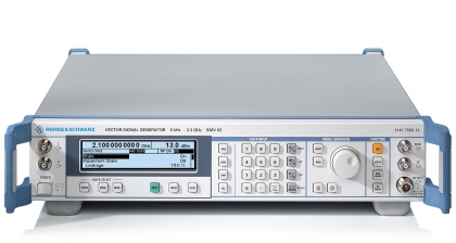
As an example, the Rohde and Schwarz SMV03 is a high-performance vector signal generator that can be equipped with an optional integrated pulse modulator. With the option, the signal generator not only delivers in-phase (I) and quadrature (Q) digitally modulated signals from 9 kHz to 3.3 GHz, but can generate pulse-modulated signals with pulse widths from 20 ns to 1 s and pulse periods from 100 ns to 85 s.
Analyzing Pulses
A pulse-modulated signal source is the starting point for a pulsed RF measurement system that also contains some form of power meter or analyzer. An RF power meter with power detector equipped for pulsed power measurements can provide simply pulsed power measurements, but typically without frequency or phase information. A spectrum analyzer such as the Keysight 8562B is an example of a broadband analyzer that can measure a wide range of pulsed waveforms. It has a nominal frequency range of 9 kHz to 22 GHz but can be extended to millimeter-wave frequencies by means of external frequency conversion components.
When both amplitude and phase information are required from pulsed RF measurements, a vector network analyzer (VNA) designed for the purpose can perform pulsed S-parameter measurements on a DUT. Such measurements are particularly useful when making on-wafer measurements, such as when evaluating RF/microwave MMIC amplifiers for pulsed signal applications. VNAs for pulsed RF measurements are capable of making triggered measurements, aligning the start of the measurement with the start of each pulse, or adjusting the amount of delay before the start of a measurement so that, for example, the peak amplitude of the pulse is measured at the pulse width midpoint.
VNAs with pulsed RF measurement capabilities typically show pulse amplitude and phase characteristics versus frequency, but can also show test results in the time domain, with pulse amplitude and phase displayed as functions of time. The measurements are made with a repetitively pulsed signal, so that data points can be taken continuously on pulse after pulse to build up details on the time-domain characteristics.
Pulsed VNA Examples
Only certain VNAs are designed for pulsed RF measurements, such as the model 37397C VNA from Anritsu and the Keysight N5242A VNA. The Anritsu 37397C VNA operates from 40 MHz to 65 GHz with four independent test ports while the Keysight N5242A covers 10 MHz to 26.5 GHz in two- and four-port versions. Both analyzers can be supplied with options for pulsed S-parameter measurements using internal or external test signal sources. Both can also be equipped with time-domain display capabilities to show pulse amplitude and phase as functions of time as well as frequency.
This has been a brief review on making pulsed RF measurements, detailing just a few of the signal generators and analyzers designed for the purpose. These pulsed RF measurements are often performed in the frequency domain, to view amplitude and phase as functions of frequency. But as noted earlier, some VNAs provide the capability to display results in the time domain as well. In some cases, it may be necessary to also know what a DUT does to the pulses themselves, such as rounding the edges of a pulse and, in those cases, it is necessary to perform pulsed measurements in the time domain, with a high-speed digital sampling oscilloscope (DSO) with sufficient bandwidth and sampling rate.
For those with further questions about pulsed RF measurements, assistance is available by contacting Axiom Test Equipment’s sales department at sales@axiomtest.com or by calling 760-806-6600.
Back to BLOG


