Shed Some Light on Solar Power Testing
May 03, 2022
 |
When Michael Faraday generated electricity in 1831 by moving a magnet within a coil of wire, he probably never imagined that sunlight could do the same thing. Electromagnetic (EM) turbines powered by fossil fuels may still be the world’s leading sources of electricity, but solar power based on photovoltaic (PV) energy is coming on strong. It is dependable and economical. However, testing PV electricity sources may pose new challenges for engineers and technicians “raised” on traditional electric power supplies. But with the right power supplies for simulation and well-equipped analyzers for investigation, a future with solar power sources such as PV cells, modules, and arrays looks bright.
Henrich Hertz discovered the photoelectric effect in 1887. He learned that sunlight could discharge electrons in certain materials, causing current to flow at some voltage. It was not until 1954 that a practical PV cell was created at Bell Labs (Berkeley Heights, NJ) by the team of Daryl Chapin, Calvin Fuller, and Gerald Pearson. It converted sunlight to electricity with about 6% efficiency. The efficiency improves with time, as modern PV cells provide conversion efficiency closer to 20%.
Arrays formed of many solar cells are often seen on the outsides of satellites, where exposure to the sun provides electricity in space. Meanwhile, PV technology is gaining wider acceptance back on Earth, as PV cells, modules, panels, and arrays are providing electricity for everything from wearable medical devices to large manufacturing facilities. Although solar electric sources produce electricity that must be measured, testing the electricity is not quite the same as testing from EM-based electric power sources. For one thing, conversion efficiency from sunlight to electricity must be gauged for PV power sources under different conditions. Many variables can affect PV conversion efficiency, but regional and global standards define the test conditions required for testing solar power devices and systems as needed for different applications.
The output of a PV energy source can be described by its current (I) versus voltage (V) characteristics. The curve formed by the I-V response varies continuously with the sun’s irradiance and other operating conditions, such as temperature and humidity. Each point in a PV I-V curve represents a distinct current and voltage or “value pair.” When testing PV devices and systems, one key parameter to be found is the open-circuit voltage, Voc, measured at an open-circuit or infinite-resistance condition. This is the maximum DC voltage exhibited by a PV device under test (DUT) with no load connected. Because there is no load, there will be no output power. Another key parameter for a PV DUT is short-circuit current, Isc, a point on the I-V curve with zero resistance, zero voltage, and zero output power. It refers to the maximum solar irradiance a PV DUT will receive and can be used to develop overcurrent protection for PV cells, panels, and arrays.
In terms of power for a PV device, the maximum power point (MPPT or Pmp) is usually along the knee of the I-V curve. The largest amount of power a PV device can produce will depend upon the device’s efficiency, the temperature, and the amount of solar irradiance. The current at the MPPT is usually referred to as the maximum power current or Imp.
Seeing the Light
Test equipment for PV cells, modules, panels, and arrays should be capable of performing the types of measurements that typically characterize such PV components and systems, including short-circuit current testing and open-circuit voltage testing, Additional PV measurement capabilities include solar responsivity or how a PV device responds to different wavelengths of light and how efficiently it can convert light to electricity.
Useful test equipment capabilities include wide I and V measurement ranges, high AC and DC power accuracy, and high resolution. Any PV-based source of electricity will require evaluation of inverter efficiency or the ratio of the inverter’s DC power input to its AC power output. A power analyzer capable of simultaneously measuring DC input power and AC output power can simplify this task. Where measurements are performed, such as in the R&D lab or production line versus in the field, will help determine the desired form factor of the test equipment. Whereas engineering and production applications are well served by standard rack-mount test units, on-site measurements of PV installations may require portability and high accuracy across wide temperature ranges since PV energy-producing setups and systems can be subjected to extreme environmental conditions. The amount of testing required will depend upon local regulations.
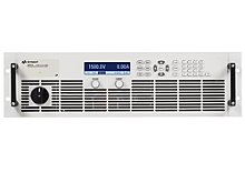
For controlling DC power levels at various points along a PV system, including at the input to the inverter, auto ranging DC power supplies such as the Keysight N8900 Series provide high resolution and accuracy across wide voltage and current ranges. For example, the Keysight N8937A provides as much as 1500 VDC, 30 A, and 15 kW when fed with a 208-VAC input. Its auto ranging output maintains voltage accuracy of better than 1.5 VDC and current accuracy within 60 mA for automatically changed combinations of current and voltage.
The Keysight N8937APV Photovoltaic/Solar Array Simulator is a DC power supply with the same test limits of 1500 VDC, 30 A, and 15 kW as the Keysight N8937A but with special software-controlled features for characterizing inverters in PV systems and arrays. It can find the MPPT and maximum converter efficiency to develop MPPT algorithms for a PV array for different environmental conditions. The Keysight N8937APV PV/solar array simulator includes algorithms for testing to the European EN50530 power standard. Models N8937A and N8937APV are each housed in a 3U-high, rack-mount enclosure and designed for 208 VAC input power. Both feature GPIB, Ethernet/LAN, USB 2.0, and analog interfaces.
Another quality power supply, built specifically for solar testing applications, is the Chroma 62150H-600S Programable DC Power Supply which outputs up to 600V and 25A, with a power level of up to 15kW. This “S” series features a powerful solar array simulation function which simulates the output characteristics of a solar array. This function is useful for MPPT performance evaluation for solar inverter testing. I-V curves can be easily created and edited.
For power analysis, the Yokogawa WT3000 Precision Power Analyzer has a current measurement range of 0.5 to 30.0 A and voltage measurement range of 15 to 1000 VDC. It provides power measurement accuracy that is within ±0.02% of the reading and ±0.04% of the measurement range, showing results on an 8.4 in. LCD screen. The analyzer includes GPIB, Ethernet, RS-232, and USB interfaces and provides the measurement precision needed for enhancing inverter efficiency in PV arrays and systems.
With greater versatility and measurement capability, the Yokogawa WT5000 Precision Power Analyzer, employs a modular architecture with seven slots for slide-in modules to adapt to changing measurement needs. It shows test results with ±0.03% or better accuracy on a 10.1-in. WXGA touchscreen and boasts AC power accuracy of 0.1% + 0.02% of the measurement range. This power analyzer incorporates as much as 32 GB internal data memory and can save harmonics to the 500th order. It includes a variety of lowpass and line filters to suppress unwanted signal components. Power waveforms are captured at 10 MSamples/s with the aid of an 18-b analog-to-digital converter (ADC). The modular construction includes connectors for multiple-unit synchronization; one master and three slaves can be connected for a total of four units operating in synchronization. In addition to optimizing PV arrays and their inverters as well as recording the charging and discharging characteristics of batteries within a PV array, the model WT5000 Precision Power Analyzer provides the measurement capabilities needed for testing inverter-driven motors for electric vehicles (EVs) and hybrid electric vehicles (HEVs).
These are just a few examples of the PV array simulators and power analyzers available from Axiom Test Equipment (www.axiomtest.com) for the design, optimization, and maintenance of PC cells, modules, and arrays. The test equipment is backed by sales and engineering professionals who can help provide the best measurement solution for a particular PV system based on the operating conditions. Ideally, a PV power source provides as much I and V as possible with the greatest efficiency possible and it is test equipment such as these Keysight and Yokogawa units that can help reach or exceed those goals.
Back to BLOG