
Agilent 81142A, Keysight 81142A, HP 81142A
Serial Pulse Data Generator, 13.5GHz
Signal Generators >> ARB, Data, Function, Pattern and Pulse >> Serial Pulse Data Generator, 13.5GHzModel: 81142A
|
Product Overview
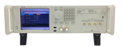
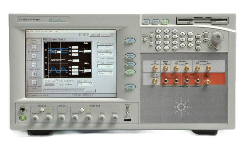
AGILENT / HP 81142A SERIAL PULSE DATA GENERATOR (Call for Availability)
The Agilent / HP 81142A Serial Pulse Data Generator enables reliable physical layer measurements for high-speed bus designs and for scientists conducting fundamental lab research. The Agilent / HP 81142A Serial Pulse Data Generator provides what is needed to conduct physical layer tests e.g. precision low jitter signals or full control of data streams for stress tests. Its linear delay modulation is essential for jitter tolerance and jitter transfer measurements.
Features and Specifications of the Agilent / HP 81142A Serial Pulse Data Generator include:
Features:
- Pulse, Data Pattern and PRBS generation up to 13.5 GHz
- Differential outputs for data, clock and trigger
- Trigger and external clock input
- Fastest transition times < 20 ps
- Data formats: NRZ, R1 and RZ
- Low jitter, high accuracy signals with Jitter < 1 ps RMS
- 1 GHz jitter modulation bandwidth
- PRBS generation from 25 -1 to 231 -1
- 32 Mbit Memory for long, "real world" patterns
- Sequencing and looping for protocol based data
- Event trigger capabilities
- Subrate clock for easy generation of reference clock
Specifications:
- Frequency: 150 MHz to 13.5 GHz
- Output channels:
- Single channel data and clock
- Differential or single ended
- Triggering:
- Aux In (Trigger In): Lets user connect a signal to switch between Pattern A and B, or to suppress the output signal
- Trigger Out: Lets user provide a trigger for another device
- Data formats: RZ, R1, NRZ
- Duty cycle: 35ps to period -35ps
- Clock/data delay range: ±0.75 ns with a 100 fs resolution
- Delay modulation range: -100 ps to 100 ps
- Transition times (10 / 90): < 25 ps
- Jitter (clock mode): 1 ps rms typical
- Jitter (data mode): 9 ps pp typical
- Jitter modulation bandwidth: DC - 1 GHz
- Data output amplitude / resolution: 0.1V to 1.8V with 5mV resolution
- Output voltage window: -2V to 3V
- Sequencing and looping: 1 level of up to 4 blocks
- Memory: 32Mbit
- Channel output connector: 2.4 mm
- Interfaces: GPIB, LAN, parallel printer, VGA, 4 x USB 2.0, 1 x USB 1.1
- Data Output (DATA OUT)
- Range of operation:
- 150 MHz to 13.5 GHz
- For RZ/R1: min. 620 MHz
- (< 620 MHz only with external clock)
- For RZ/R1/pulse up to 13.5 GHz
- Frequency accuracy: ± 15 ppm typical
- Width accuracy: ± 20 ps
- Format: NRZ, normal or inverted, RZ, R1
- Amplitude/resolution: 0.10 V to 1.8 V, 5 mV step
- Output voltage window: -2.0 V to +3.0 V
- Predefined levels: ECL, PECL (3.3 V), LVDS, CML
- Transition times:
- (20% to 80%) < 20 ps
- (10% to 90%) < 25 ps
- Low intrinsic jitter: 9 pspp typical
- Clock/data delay range: ±0.75 ns in 100 fs steps
- External termination voltage: -2.0 V to +3.0 V
- Crossing point: Adjustable from 20% to 80% typical
- RZ/R1 width: 70 ps to period -70 ps
- Pulse width: 35 ps to period -35 ps
- Single error inject: Adds single errors on demand
- Fixed error inject: Fixed error ratios of 1 error in 10n bits, n = 1...12
- Interface: Differential or single-ended, DC coupled, 50 Ω
- Connector: 2.4 mm female
- Clock Output (CLK OUT)
- Amplitude/resolution: 0.1 Vpp to 1.8 Vpp, 5 mV steps
- Output voltage window: -2.00 V to +2.8 V
- Transition times:
- (20% to 80%) < 20 ps
- (10% to 90%) < 25 ps
- External termination voltage: -2.0 V to +3.0 V
- Jitter: < 1 psrms typical
- Interface: Differential or single-ended, DC coupled, 50 Ω output impedance
- Connector: 2.4 mm female
- Subrate Clock Output (SUB CLK OUT)
- Used to generate reference clocks that are subrates of the data rate
- Divider factors: N = 2,3 ... 128
- Levels:
- High: + 0.5 V
- Low: - 0.5 V typical
- Transition times: 35 ps typical
- Interface: DC coupled, 50 Ω
- Connector: SMA female
- Clock Input (CLK IN)
- Uses an external clock as a generator clock
- Amplitude: 200 mV to 2 V
- Interface: AC coupled, 50 Ω nominal
- Connector: SMA female, front panel
- 10 MHz Reference Input (10 MHZ REF IN)
- If a 10 MHz reference clock is applied, the PLL generating the internal clock for the generator clock will lock to the applied signal
- Amplitude: 200 mV to 2 V
- Interface: AC coupled, 50 Ω nominal
- Connector: BNC, rear panel
- 10 MHz Reference Output (10 MHZ REF OUT)
- Uses an external clock as a generator clock
- Amplitude: 1 V into 50 Ω typical
- Interface: AC coupled, 50 Ω output impedance
- Connector: BNC, rear panel
- Delay Control Input (DELAY CTRL IN)
- External signal applied to Delay Control Input varies the delay between Data Output and Clock Output
- This can be used to generate jittered signals to stress the device under test
- Range: -100 ps to +100 ps
- Sensitivity: 400 ps/V typical
- Linearity: ±5% typical
- 3dB modulation bandwidth: DC to 1 GHz
- Levels: -250 mV to +250 mV
- Interface: DC coupled, 50 Ω nominal
- Connector: SMA female
- Error Add Input (ERROR ADD)
- Adds a single error to the data output for each rising edge at the input
- Levels: TTL compatible
- Interface: DC coupled, 50 Ω nominal
- Connector: SMA female
- Trigger Output (TRIGGER OUT)
- Provides a trigger signal synchronized with the pattern
- For use with an oscilloscope or other test equipment
- Pulse width: Square wave
- Transition times: 35 ps typical
- Levels:
- High: +0.5 V
- Low: -0.5 V typical
- Interface: DC coupled, 50 Ω nominal, single ended or differential
- Connector: SMA female
- AUX Input (AUX IN)(Trigger In)
- When the Alternative Pattern Mode is activated the memory will be split into tow parts
- User can define a pattern for each part
- Levels: TTL compatible
- Interface: DC coupled, 50 Ω nominal
- Connector: SMA female
Other model in this series:
REQUEST A QUOTE
| Testimonials |
|
Got wonderful experience with Axiom. They have all the devices we need and the lady is very helpful during the usage. I accidentally dropped an important item in the package during equipment return. The lady Geri happened to find it and sent it back! Both great thanks to Geri and their team! -- Kevin H. San Jose, CA |