
Stanford Research SR560
Low Noise Voltage Preamplifier
Amplifiers - RF and Microwave >> Accessories and Other >> Low Noise Voltage PreamplifierModel: SR560
 CLICK TO ENLARGE
 |
|
Available Option Configurations
Config-01
- No Options Included
MSRP: $3,095 |
In Stock! GET QUOTE
Config-01
Product Overview
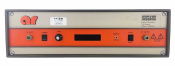
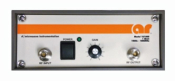
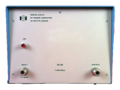
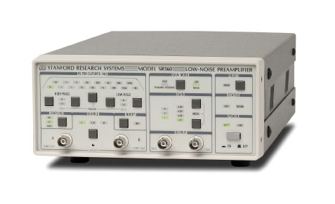
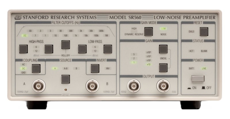
STANFORD RESEARCH SR560
The Stanford Research SR560 is a high-performance, low-noise preamplifier that is ideal for a wide variety of applications including low-temperature measurements, optical detection, and audio engineering.
The SR560 has a differential front end with 4 nV/√Hz input noise and an input impedance of 100 MΩ. Complete noise figure contours are shown in the graphs below. The SR560's inputs are fully floating (BNC shields are not connected to chassis ground). Both the amplifier ground and the chassis ground are available on the rear panel for flexibility in grounding the instrument. Input offset nulling is accomplished by a front-panel potentiometer, accessible with a small screwdriver.
In addition to the signal inputs, a rear-panel TTL blanking input lets you quickly turn off and on the instrument's gain. This is useful in preventing front-end overloading. The gain turns off 5 µs after the TTL level goes high, and back on again within 10 µs after the TTL signal goes low.
Two insulated output BNC connectors provide 600 Ω and 50 Ω outputs. Both are capable of driving 10 Vpp into their respective loads. Two rear-panel power supply outputs provide up to 200 mA of ±12 VDC referenced to the amplifier ground. The outputs provide clean DC power for use as a bias source.
Gains are selectable from 1 to 50,000 in a 1-2-5 sequence. An adjustable gain feature lets you specify the gain as a percentage of any of the fixed gain settings with 0.5 % resolution. Gain can be selectively allocated before the filters to optimize noise performance, or after the filters to reduce susceptibility to overloads.
The SR560 contains two first-order RC filters whose cutoff frequency and type (HPF or LPF) can be configured from the front panel. Together, the filters can be configured as a 6 or 12 dB/oct rolloff low-pass or high-pass filter, or as a 6 dB/oct rolloff band-pass filter. A filter reset button is included to shorten the overload recovery time of the instrument when long filter time constants are being used. Filter cutoff frequencies can be set in a 1-3-10 sequence from 0.03 Hz to 1 MHz.
Three internal, rechargeable, lead-acid batteries provide up to 15 hours of battery powered operation. An internal battery charger automatically charges the batteries when the unit is connected to the line. The charger senses the battery state and adjusts the charging rate accordingly. Two rear-panel LEDs indicate the charge state of the batteries. When the batteries become discharged, they are automatically disconnected from the amplifier circuit to avoid battery damage.
The microprocessor that runs the SR560 is "asleep" except during the brief interval it takes to change the instrument's setup. This ensures that no digital noise will contaminate low-level analog signals.
The RS-232 interface allows listen-only communication with the SR560 at 9600 baud. Up to four SR560s can be controlled from a single computer, with each SR560 being assigned a unique address. A "Listen" command specifies which SR560 will respond to commands on the RS-232 line. All functions of the instrument (except power on) can be set via the RS-232 interface. The RS-232 interface electronics are opto-isolated from the amplifier circuitry to provide maximum noise immunity.
Specifications of the Stanford Research SR560 include:
INPUT
Inputs: AC or DC coupled, single-ended or differential
Input impedance :100 MΩ + 25 pF
Maximum input: 3 Vpp
CMRR: 100 dB from DC to 1 kHz (100 mVrms common mode input at 1kHz , gain=100, low noise mode. Decreases by 6 dB/octave from 1 kHz to 1 MHz)
Noise: 4 nV/√Hz at 1 kHz
Gain: 1 to 50,000 in 1-2-5 sequence. Vernier gain in 0.5 % steps.
Gain stability: 200 ppm/°C
Bandwidth: -3 dB at 1.2 MHz (typ.)
Flatness: ±0.3 dB to 300 kHz (gains up to 1000)
FILTERS
Signal filters: 2 configurable (low-pass or high-pass) 6 dB/oct rolloff filters. -3 dB points are settable in a 1-3-10 sequence from 0.03 Hz to 1 MHz.
Gain allocation:
High Dynamic Reserve — Gain is increased after the signal filters to prevent overloading.
Low Noise — Gain is increased before the filters to improve noise figure.
OUTPUT
Maximum output: 10 Vpp into 50 Ω and 600 Ω
Filter reset: Long time constant filters may be reset with front-panel button.
DC drift: 5 µV/°C referred to input (DC coupled)
Distortion: 0.01 % at 1 kHz
Rear panel: ±12 VDC @ 200 mA referenced to amplifier ground
REQUEST A QUOTE
| Testimonials |
|
Axiom has been a huge help to our success in the high demand of Silicon Valley. We are pleased to continue to work with Axiom for our equipment needs. -- Tony W. Newark, CA |